Example: Using Energy Balance: Reactor Inlets
In this example, we show how to deal with two special cases for Energy Balance models.
One is for a batch reactor having inflows; another is a CSTR train with intermediate feed between the reactors. These situations need additional specifications. For outflows such as with Batch outflows or for CSTR separation streams, no special specifications are needed.
To get started, please import the EnergyBalance_Batch.rex and EnergyBalance_CSTR.rex files from the Optience Corporation\REX Suite\REX Examples folder. These are based on the Hydroformylation of 1-Octene example, with the addition of Heat of Formation and Specific Heat (Cp) data which are required for the energy balance.
Batch Reactor with Inflows
One is for a batch reactor having inflows; another is a CSTR train with intermediate feed between the reactors. These situations need additional specifications. For outflows such as with Batch outflows or for CSTR separation streams, no special specifications are needed.
To get started, please import the EnergyBalance_Batch.rex and EnergyBalance_CSTR.rex files from the Optience Corporation\REX Suite\REX Examples folder. These are based on the Hydroformylation of 1-Octene example, with the addition of Heat of Formation and Specific Heat (Cp) data which are required for the energy balance.
This batch example is in EnergyBalance_Batch.rex file. The Energy balance feature is enabled by setting Use Energy Balance for Temperature in the Reactor node.
In the Experiments node, only Set1 is included for which the initial Temperature is set to 373K. After running the simulation you can inspect the temperature profiles in the Model-Data Comparison node.
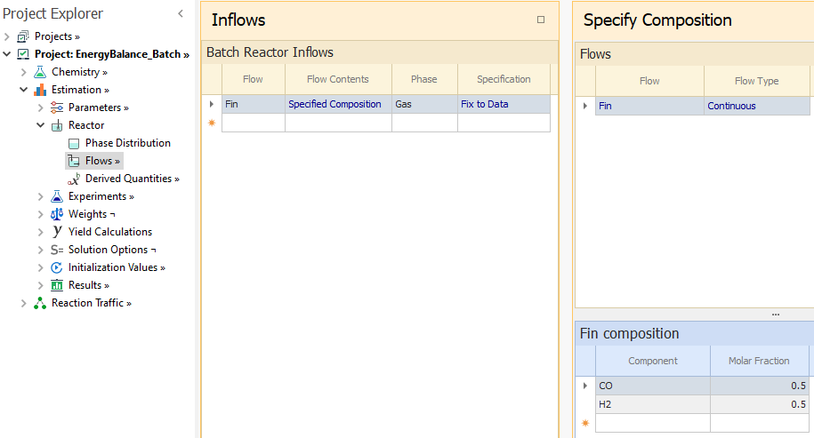
Now we will add a continuous inlet flow of equimolar CO and H2 gas. In the Reactor node, change the Fedbatch Flows to Yes. In addition, you must specify the phase of the inlet flow in order to compute the enthalpy of the inflow moles. So in the Flows node, we have entered Fin as the inflow whose Phase is assigned as Gas:
The equimolar CO and H2 content of the inflow is set in the Composition view of the Flows node.
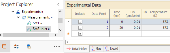
Now please go to Experiments node and include Set2-Inlet.
That set has the same specifications as Set1, except that it has nonzero values for the Fin flow. The temperature of the inflow must also be entered for the Energy Balance:
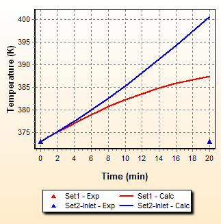
After rerunning the simulation, you can compare the profiles in Model-Data Comparison node.
Note the higher reactor temperature for Set2. This is due to the continuous addition of CO and H2 reactants through Fin, resulting in higher octene conversion and thus more heat released by that reaction:
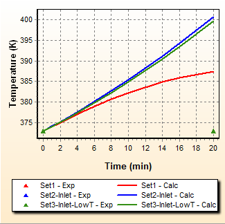
Lets see the effect of a different inflow temperature by including Set3-Inlet-LowT in the Experiments node. This set has everything same as Set2-Inlet, except for a lower inflow temperature. The temperature increase is smaller than in Set2, as a result of the colder inlet:
As for the batch outflows when enabling energy balance, the temperature of the outlet streams are always considered the same as the reactor. So there is no need to set the outflow temperature. The only requirement is for a specified composition outflow. For such outflows, you must define the outflow phase when using the energy balance model in order to calculate the enthalpy of the moles leaving the reactor.
In the Experiments node, only Set1 is included for which the initial Temperature is set to 373K. After running the simulation you can inspect the temperature profiles in the Model-Data Comparison node.
Now we will add a continuous inlet flow of equimolar CO and H2 gas. In the Reactor node, change the Fedbatch Flows to Yes. In addition, you must specify the phase of the inlet flow in order to compute the enthalpy of the inflow moles. So in the Flows node, we have entered Fin as the inflow whose Phase is assigned as Gas:
|
|---|
The equimolar CO and H2 content of the inflow is set in the Composition view of the Flows node.
Now please go to Experiments node and include Set2-Inlet.
That set has the same specifications as Set1, except that it has nonzero values for the Fin flow. The temperature of the inflow must also be entered for the Energy Balance:
|
|---|
After rerunning the simulation, you can compare the profiles in Model-Data Comparison node.
Note the higher reactor temperature for Set2. This is due to the continuous addition of CO and H2 reactants through Fin, resulting in higher octene conversion and thus more heat released by that reaction:
|
|---|
Lets see the effect of a different inflow temperature by including Set3-Inlet-LowT in the Experiments node. This set has everything same as Set2-Inlet, except for a lower inflow temperature. The temperature increase is smaller than in Set2, as a result of the colder inlet:
|
|---|
As for the batch outflows when enabling energy balance, the temperature of the outlet streams are always considered the same as the reactor. So there is no need to set the outflow temperature. The only requirement is for a specified composition outflow. For such outflows, you must define the outflow phase when using the energy balance model in order to calculate the enthalpy of the moles leaving the reactor.
CSTR Reactor with Intermediate Feed
The CSTR example is in EnergyBalance_CSTR.rex file. It consists of two CSTR reactors in series with energy balance enabled. In the Experiments node, only Set1 is included for which the entry Temperature is set to 373K. You may visualize the calculated Temperature trend in the Model-Data Comparison node.
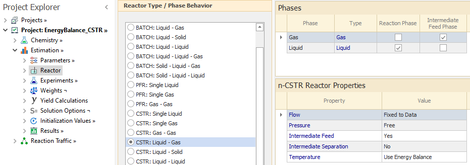
Next, we will simulate the effect of feeding CO & H2 between the first and the second reactor. To do that, set Intermediate Feed to Yes in the Reactor node. You must also specify the phase of the intermediate feed for energy balance. In this case, Gas is selected:
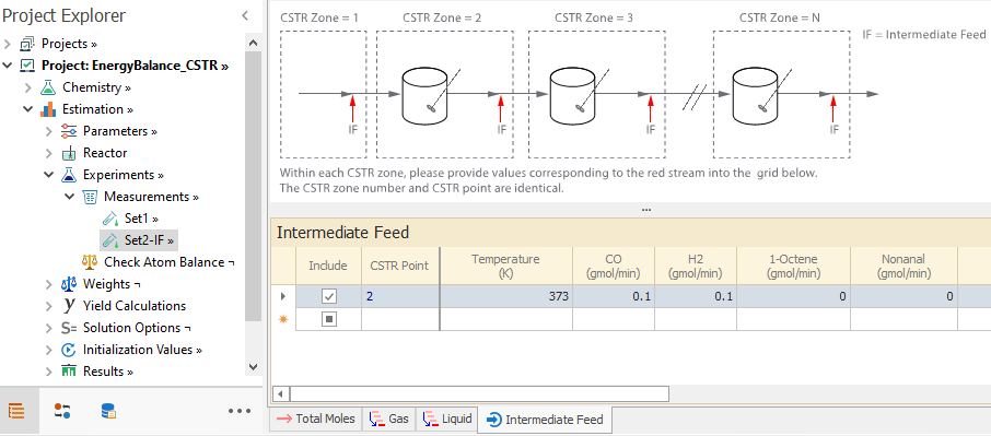
Now, please go to Experiments node and include Set2-IF. This set has the same specifications as Set1, except for the addition of 0.1 gmol/min of CO and H2 between the two reactors as shown in the in the Intermediate Feed tab for Set2-IF. Since energy balance is enabled, the temperature of the feed must be specified. We set it to 373K, same as the feed to the first reactor:
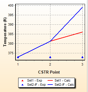
After rerunning the simulation, you can compare the profiles in Model-Data Comparison node:
Temperature is same at points 1 and 2 (Fresh feed and outlet of first reactor, respectively). However for point 3 (outlet of second reactor), there is higher temperature value for Set2. This is due to higher octene conversion and thus increased reaction heat released.
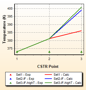
Now we try a higher temperature for the Intermediate Feed. Please include Set3-IF-highT in the Experiments node. This set has everything same as Set2-IF, except for a higher temperature for the Intermediate Feed. After running the simulation, we see higher temperature at the second reactor outlet compared to Set2-IF:
As for Intermediate Separation for multiple CSTR reactors, no extra specifications are necessary for energy balance calculations. A few notes below for the two types of separation allowed:
Next, we will simulate the effect of feeding CO & H2 between the first and the second reactor. To do that, set Intermediate Feed to Yes in the Reactor node. You must also specify the phase of the intermediate feed for energy balance. In this case, Gas is selected:
|
|---|
Now, please go to Experiments node and include Set2-IF. This set has the same specifications as Set1, except for the addition of 0.1 gmol/min of CO and H2 between the two reactors as shown in the in the Intermediate Feed tab for Set2-IF. Since energy balance is enabled, the temperature of the feed must be specified. We set it to 373K, same as the feed to the first reactor:
|
|---|
After rerunning the simulation, you can compare the profiles in Model-Data Comparison node:
|
|---|
Temperature is same at points 1 and 2 (Fresh feed and outlet of first reactor, respectively). However for point 3 (outlet of second reactor), there is higher temperature value for Set2. This is due to higher octene conversion and thus increased reaction heat released.
Now we try a higher temperature for the Intermediate Feed. Please include Set3-IF-highT in the Experiments node. This set has everything same as Set2-IF, except for a higher temperature for the Intermediate Feed. After running the simulation, we see higher temperature at the second reactor outlet compared to Set2-IF:
|
|---|
As for Intermediate Separation for multiple CSTR reactors, no extra specifications are necessary for energy balance calculations. A few notes below for the two types of separation allowed:
- Phase Based: The temperature of the outlet is assumed to be same as the reactor. Also, the phase where the moles come from is always specified for this option irrespective of whether energy balance calculations are enabled or not.
- Overall Based: The temperature of the outlet is assumed to be same as the reactor. For multiphase reactors, no specification of phase for the moles removed is necessary, because each compound is extracted proportionally to its availability in the phases. The only difference is for the special Gas-Gas(membrane) reactor, where compounds are only removed from the reaction phase. So it is not required to specify from which phase the compounds are removed.
Top of Topic
Go back to: